Last year we spend a significant amount of time recording the wreckage of the Successful, a late 19th/early 20th century fishing trawler (see Field Report 4). It is a very complex shipwreck, and we were unable to fully document it in one field season. The fact that we can only work on the wreck at low tide makes this task even more challenging. This year, we have re-visited the wreck and cleared it of a year’s growth of kelp and seaweed, in order to continue its documentation.
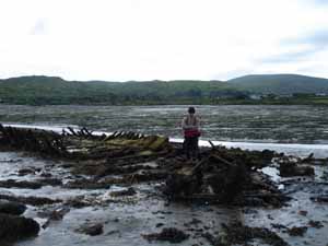
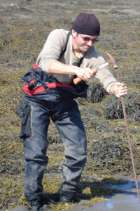
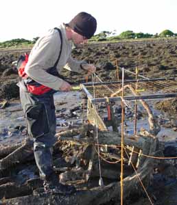
The rudder and steering assembly on this ship was quite complex and well-preserved. We did not have time to fully investigate this feature of the shipwreck last year, and I’m interested in spending some time recording it, to better understand its construction and operation. Kevin and I spend two days preparing for and starting a detailed drawing of this feature. Here Kevin spends some time studying this complicated feature, located at the stern of the vessel.
The rudder, seen directly in front of Kevin, consisted of a wooden blade attached by iron straps to a massive vertical iron shaft.
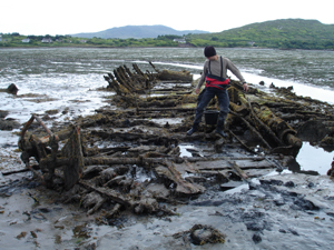
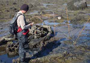
At the top of the rod, the rudder head was attached via a crosshead and guide-rods to a yoke attached to a barrel-like fitting which in turn was bolted to the deck. Pinned underneath this steering assembly are collapsed timbers of the upper stern.
To accurately record the details of the steering assembly, we have decided to suspend a leveled planning frame directly above the feature. This is a rigid square, 1 meter by 1 meter, with string stretched across to form a grid with 10 cm intervals. It is a useful guide when drawing a complicated object such as this. The first step is to hammer in rebar which will be used to support the planning frame.
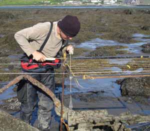
Once the planning frame is suspended over the section of the feature which we wish to draw first, we are ready to get started. The frame has to be high off the ground because the components of the steering mechanisms rise a significant height from the seafloor. This makes the frame more susceptible to being moved by the high winds common to Achill, thus the extra rebar to help stabilize it.
Kevin uses a plumb bob to pinpoint the exact spot he is measuring, and then a folding ruler in conjunction with the string guidelines to measure its x – y coordinates. He calls these out to Chuck, who is making a scaled drawing of the steering assembly one square meter at a time.
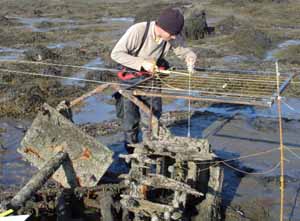
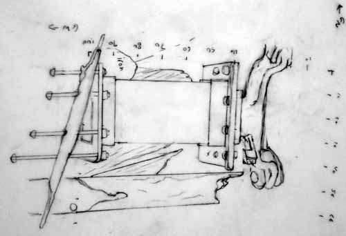
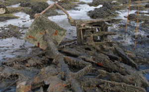
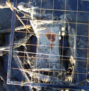
The view looking down through the planning frame. The rectangular iron object is the fitting that was bolted to the deck. A geared yoke attached to its upper surface was acted upon by the steering wheel (no longer extant). The yoke turned a pair of guide-rods which rotated the rudder shaft, turning the rudder blade to port or starboard.
The field drawing of the square meter we finished today. While drawn to scale, it is still a rough sketch that will be refined and adjusted as we process more data in the post-fieldwork phase of the project. We are planning on continuing to use the planning frame to record more of the steering equipment, which will then be plotted on the main map of the site.